Manual & Safety
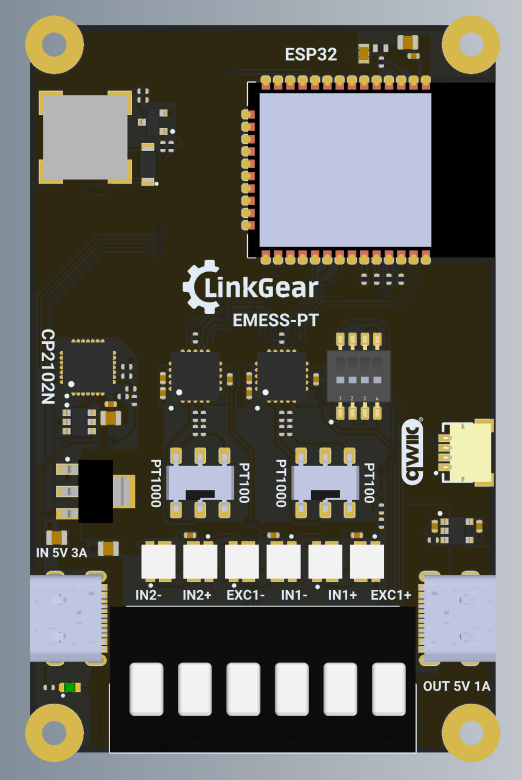
LinkGear EMESS-PT 100/1000 Sensor Board for ESPHome
Model EMEPT1
Thank you for choosing the LinkGear EMESS-PT Sensor Board for ESPHome.
Package Contents1 x LinkGear EMESS-PT 100/1000 |
WARNINGS & Safety Information
- Before using the device, carefully read this manual.
- Keep this manual downloaded or printed in a safe place for later use.
- Never connect the device to 230/110 V mains voltage.
- Avoid placing objects on the PCB that could short any exposed connections.
- Securely connect all probe and power cables before operation.
- Only use a suitable 5 V USB-C power supply.
- The device should not be opened or repaired by unauthorized personnel.
- The device must not be used in wet or humid environments.
- Disconnect power before changing wiring or DIP switch settings.
- This device is not for medical applications or any safety-critical use.
- Only use the left-side USB to power the device and only use the right-side USB to power-passthrough.
Technical Specification
| Input voltage/current | 5 V via USB-C |
| Microcontroller | ESP32-WROOM-32E (8 MB), pre-flashed with ESPHome |
| RTD interfaces | 2 x MAX31865 channels for PT100/PT1000 probes |
| Supported probe modes | 2 x 2-wire, or 1 x 2-wire together with 1 x 3-wire or 4-wire |
| Configuration | DIP switch selectable PT100/PT1000 and 2-wire/3-wire/4-wire operation without soldering |
| LEDs | 6 individually addressable SK6812 LEDs |
| Buzzer | Passive buzzer for configurable alarm output |
| Terminals | Screwless spring clamp terminals |
| Power passthrough | USB-C power passthrough (1A e-fused) |
| USB to Serial Chipset | Silicon Labs CP2102N |
| Safety Standard Compliance | CE, RoHS compliant |
Compliance

Additional compliance labels for your region may be found on the packaging or the device itself.
Installation
The LinkGear EMESS-PT comes pre-flashed with ESPHome. To connect the device to your network and modify the configuration, adopt it in ESPHome Builder or use the LinkGear Web Flasher.
Connecting to WiFi
The recommended method is using Improv over serial or Bluetooth. Alternatively, you can use the onboard access point and open 192.168.4.1 in your browser.
Connecting via Serial
If the serial port does not open on your computer, install the CP2102N driver from Silicon Labs.
Operation
The board is designed for continuous operation from a stable 5 V USB-C power supply. It powers on as soon as external power is connected.
Default Configuration
The default firmware ships with the right side as channel 1 on GPIO5 configured for a 3-wire PT100 probe, and the left side as channel 2 on GPIO4 configured for a 2-wire PT1000 probe.
| Channel | CS Pin | Default Probe Type | Default Wiring |
| Right / Channel 1 | GPIO5 | PT100 | 3-wire |
| Left / Channel 2 | GPIO4 | PT1000 | 2-wire |
DIP-Switch Settings (Channel 2)
Please make sure the dip-switches are set according to your sensor to avoid damage to the sensor or the board.
| Sensor Type | DIP 1 | DIP 2 | DIP 3 | DIP 4 |
| 2-Wire | ON | OFF | OFF | ON |
| 3-Wire | ON | OFF | ON | OFF |
| 4-Wire | OFF | ON | OFF | OFF |
Changing PT Type or Wiring
After adopting the device in ESPHome Builder, update the max31865 settings to match the DIP switch positions and connected probe type.
sensor:
  - platform: max31865
    name: "Right RTD Temperature"
    cs_pin: GPIO5
    rtd_nominal_resistance: 100.0
    reference_resistance: 400.0
    rtd_wires: 3

  - platform: max31865
    name: "Left RTD Temperature"
    cs_pin: GPIO4
    rtd_nominal_resistance: 1000.0
    reference_resistance: 4000.0
rtd_wires: 2- For PT100 use
rtd_nominal_resistance: 100.0andreference_resistance: 400.0. - For PT1000 use
rtd_nominal_resistance: 1000.0andreference_resistance: 4000.0. - For 2-wire use
rtd_wires: 2. - Use
rtd_wires: 3orrtd_wires: 4for 3-wire or 4-wire probes.
Pinout
| uC Pin | Function |
|---|---|
| GPIO22 | I2C SCL |
| GPIO21 | I2C SDA |
| GPIO23 | SPI MOSI |
| GPIO19 | SPI MISO |
| GPIO18 | SPI SCK |
| GPIO5 | MAX31865 right side CS |
| GPIO4 | MAX31865 left side CS |
| GPIO17 | SK6812 LED data |
| GPIO25 | Buzzer |
Flashing Firmware
This device can be flashed over serial. The simplest option is the LinkGear Web Flasher.
Maintenance
Keep the device clean using a dry, lint-free cloth. Do not use harsh chemicals or abrasive materials. Never clean connected probes or the PCB with pressurized air or liquids while powered.
No comments to display
No comments to display